LED message display
circuit diagram
Download pdf:
Moving
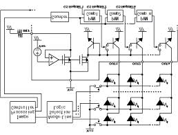
Message Display System An EPROM is be used to
store the message to be displayed on the LED display. Bits D0 to D6
from the EPROM output correspond to the seven LEDs in one column of
the display. A high output turns an LED on, the LED display being a
common cathode type. The MSB, D7, is used to reset the system when
the end of the message is reached; when it is high the system resets.
LED-BASED MESSAGE DI - circut
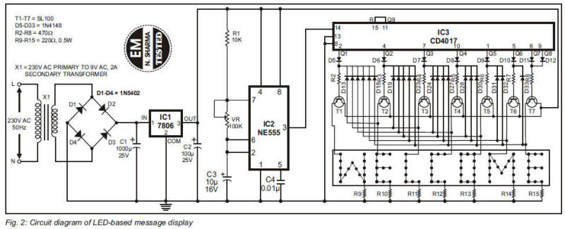
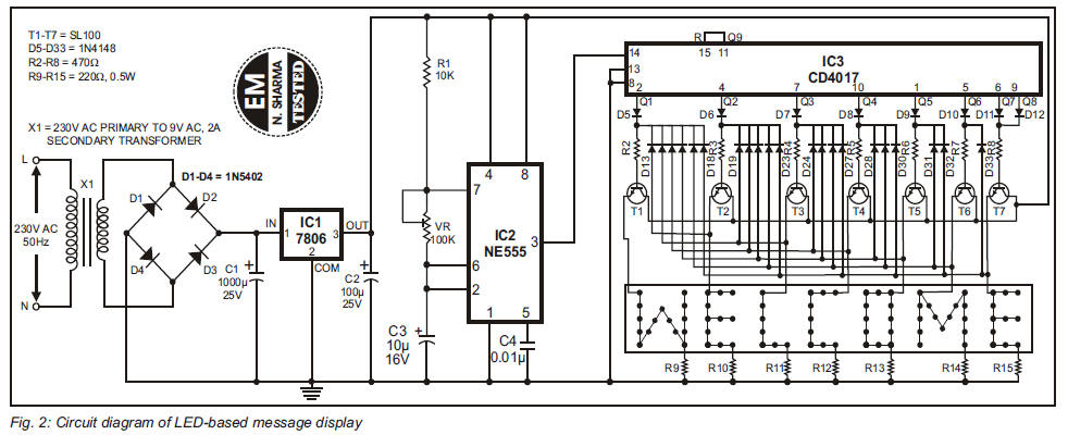
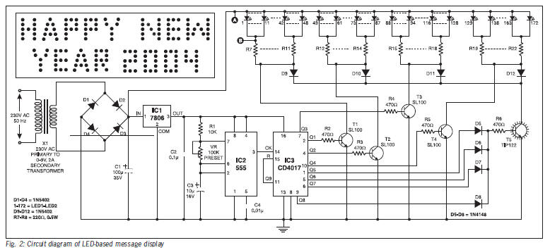
LEDs are advantageous due to their smaller size and low current
consumption. Here is a running message display circuit wherein the
letters formed by LED arrangement light up progressively. Once all
the letters of the message have been lit up, the circuit gets reset.
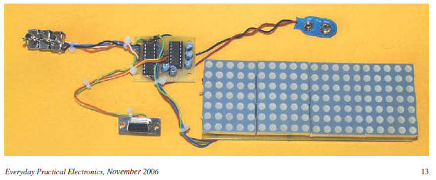
This message display circuit is built around readily available, low
cost components. It is easy to fabricate and makes use of 3mm red
LEDs. A total of 80 LEDs have been used to display the message “WELCOME”.
Scrolling LED sign
The LEDMATRIX interface
The goal of this LEDMATRIX project was to build a 80x32 pixel
display by arranging the displays in two rows with 5 displays each
giving a total of 16*16*2*2*5 = 5120 LEDs to be controlled
individually.
LED Sign with MMC Memory card
The principle of operation is simple you
have just 160 bits shift register with drivers for LEDs. I removed
the old CPU from the LED sign and connected a couple of wires to the
shift register (column driver) and the row driver to an ATMega128.
The main reason why I chose to use an ATMega128 was the need of a
large amount of RAM. I decided to use a MMC memory card to store all
the messages for 3 reasons: low cost, SPI interface and a lot of
space for messages.
Z86E04-Based RS-232 Controlled Moving Message Display
The
principle of operation is simple you have just 160 bits shift
register with drivers for LEDs. I removed the old CPU from the LED
sign and connected a couple of wires to the shift register (column
driver) and the row driver to an ATMega128. The main reason why I
chose to use an ATMega128 was the need of a large amount of RAM. I
decided to use a MMC memory card to store all the messages for 3
reasons: low cost, SPI interface and a lot of space for messages.
LED DISPLAY CONTROLLER
MULTICOLOUR LED DISPLAY
Giant LED Message Display
THIS Giant LED Message Display unit provides the
following functions: Moving message and graphics display
Static message display Animation display It is in modular form
and can be built pretty much to what ever size and format one
prefers, as discussed later. It is PIC microcontroller controlled,
programmable for its displays type and content from a PC computer.
In
vehicle LED message display system
The prototype of the display consists of eleven
display sections, each consisting of a 5x7 LED matrix. The design
allows these modular sections to be added or removed to vary the
length of the display required. The research into existing LED
displays revealed a number of equally suited products was available,
however, the goal of the project was the creation of an original
design that could be manufactured into a new product in the future.
The display is controlled by a PIC microcontroller that outputs
serial data to a series of cascaded serial-in parallel-out shift
registers. The shift registers convert the stream of serial data to
a parallel sequence used to scan each line of the display.
LED Running Message Display using CD4017 with transistor
drivers rather than a CPU
Running Message Display
RUNNING MESSAGE DISPLAY
Running Message Display
techniques are included to drive the LED
display from a
microcontroller as well as some test results ...... Figure 19 shows
the overall schematic of
the application. Scoreboards have
different purposes with various features. Scoreboards are typically
used for displaying scores of a game played between two teams. These
games can be a timed or an untimed event. The application described
in this application report creates a multi-sport scoreboard that is
cost efficient, portable, and easy to use. The display values on the
scoreboard are transmitted wirelessly. This application report
describes the selection of the following: an appropriate LED
display, a controller system, a communication system, and software
for building the wireless LED-based scoreboard. Different techniques
are included to drive the LED display from a microcontroller as well
as some test results. This application report is only for displaying
numerals on the scoreboard but the same concept can be applied to
display alphabets. A similar concept can be extended to large
LED-display modules with multiple 16 × 16 or 24 × 24 matrice
16-Channel, 12-Bit PWM LED Driver
with 6-Bit Dot Correction and ...
Typical Application Circuit (Multiple
Daisy-Chained TLC5944s). 1. Please be ... The TLC5944 has three
error detection circuits for LED open
detection (LOD), a. Monochrome, Multicolor, Full-Color LED •
Continuous Base LED Open Detection (LOD): Displays Using
Multiplexing System • LED Signboards Using Multiplexing System
LED message display
circuit
diagram
schematics free electronic circuits diagram wiring design plans
schema DIY projects handbook guide tutorial schematico electrónico
schématique diagrama esquemático projeto elektronisch schematisch
schaltplan schematy circuito shema схема skematisk
Schaltbild schematisk schaltung application manual how to make build |