DC permanent Magnet Motor speed Control
schematic
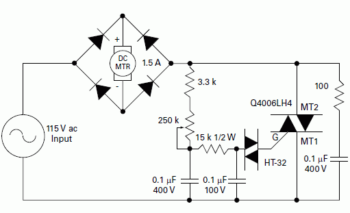
Figure illustrates a schematic for phase controlling a
permanent magnet (PM) motor. Since PM motors are also
generators, they have characteristics that make them
difficult for a standard Triac to commutate properly.
Control of a PM motor is easily accomplished by using an
alternistor Triac with enhanced commutating characteristics.
PM motors normally require full-wave DC rectification.
Therefore, the alternistor Triac controller should be
connected in series with the AC input side of the rectifier
bridge. The possible alternative of putting an SCR
controller in series with the motor on the DC side of the
rectifier bridge can be a challenge when it comes to timing
and delayed turn-on near the end of the half cycle.
The alternistor Triac controller shown in figure offers a
wide range control so that the alternistror Triac can be
triggered at a small conduction angle or low motor speed;
the rectifiers and alternistors should have similar voltage
ratings, with all based on line voltage and actual motor
load requirements.
|
