White LED driver constant current
non isolated transfomerless 230V circuit diagram
Download: VIPower: Offline constant current LED driver using
VIPer12/22A http://www.st.com/web/en/resource/technical/document/application_note/CD00012203.pdf
A lower cost alternative to the isolated VIPer12A power supply is
to use the VIPer22A in a non-isolated transformerless Buck configuration. The White
LED driver constant current non isolated 230V (90-246 V AC) circuit
diagram uses fewer and less expensive parts for systems that do not
require safety isolation.
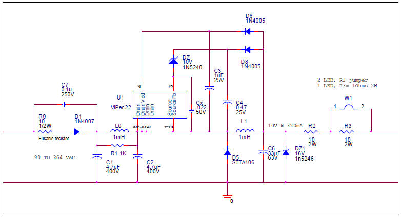
Non-isolated buck configuration scircuit diagram C1, L0, and C2
form an EMI filter to meet emission standards. D6, C3 maintain
voltage for Vdd. L1 and C6 form the output filter to average the DC
output. The output is voltage regulated at 10V by the zener diode
DZ1. R2 drops the voltage and sets the current to approximately
330mA. A different value resistor can be used to set the current to
a value up to 370mA which is the limiting factor of L1, the output
inductor.
This unit will drive 2 LEDs or 1 LED by cutting one jumper before
use. To drive 1 LED only, the jumper can be cut, placing a second
resistor in series with the output to drop additional voltage. This
is not as efficient as the previous design but simpler and less
expensive. The output is set to 10V because that is the minimum
output voltage that will drive the VIPer22A with these minimum parts.
With the addition of an inductor, 2 of 1N4005 and a small capacitor,
a lower voltage can be designed to increase the efficiency.
|
