Flashing led circuit diagram
Download:
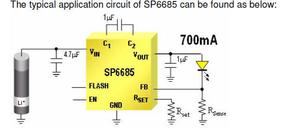
Design Considerations For Cell
Phone Camera Flash Drivers
voltage necessary for Xenon lamps, LED
flash only
needs 3.5V-4.6V constant ...LED flash driver circuits can
be sorted into CV mode (constant voltage) and.
ED flash is used popularly in the cell phone field. In contrast
to the high voltage necessary for Xenon lamps, LED flash only needs
3.5V-4.6V constant voltage. And 2000mcd- 7500mcd brightness can be
achieved with as little as 120-250mA LED current. LEDs are a good
choice for cell phone, digital camera and other portable equipment,
because LED flash has the following advantage: high efficiency, low
cost, and small PCB area. Solution for LED flash driver LED flash
driver circuits can be sorted into CV mode (constant voltage) and CC
mode (constant current) power circuits, according to the different
output characteristic of each mode. Furthermore, the LED driver
power solutions can again be sorted into the
Dual LED
Flasher Using
a 555 Timer
Explanation: R1, R2, R3, C1, and the supply voltage
determine the flash rate.
... cycle of the circuit (the
time LED 2
is on divided by the period of the cycle.
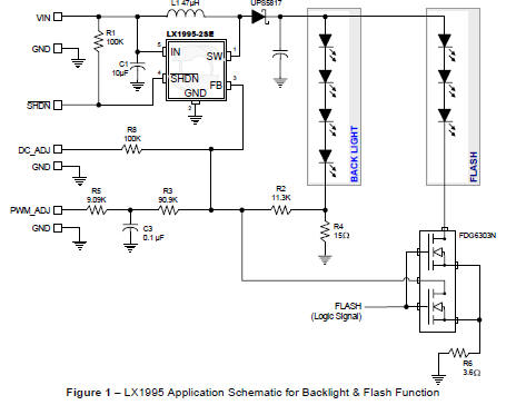
LX1995 LED DRIVER:
CAMERA FLASH APPLICATION
AN-30
Many
of these cameras utilize an LED
flash that
helps illuminate the ... two separate LED driver circuits;
however, if the LCD illumination can ...
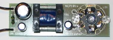
AND8224/D NCP101x LED
Flasher with
Luxeon V Star LED
Overload, Short Circuit and
Thermal Protected ... The timing of the flashingperiod
is given by the VCC ... Complete Schematic
Diagram of
the LED
Flasher. D1.
FA-250 LED L-864
LP MEDIUM INTENSITY FLASHING RED ...
The FA-250LED L-864 LP controller provides flash ...
Extremely high flux, compact LEDs mounted
on a ... LED failure
sensing circuit de-energizes
the light if.
Circuit design
for LED monitoring
system
Jul 31, 2014 ... We
had to design a Led
circuit that
would contain multiple Leds,
activate them by address, then holds the flashing addressed Led in
memory ...
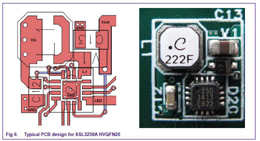
AN10733 Photo flash
LED driver
The
SSL3250A is an asynchronous boost photo flash dual LEDdriver
.... To enable control of the TX-Mask feature either circuit connection
in ...
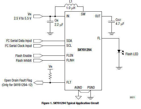
SKY81294: 1.5 A Single Flash
LED Driver
with I2C Control Interface
Over-voltage
protection (open LED,
open circuit).
- Short circuit ...
The SKY81294 maintains the flash
LED output
current using a. DC-DC ...The SKY81294 is a high-efficiency,
1.5 A high-current boost converter with a programmable
constant current. The device is intended for LED photo flash
applications in all single-cell Li-Ion powered portable
products.
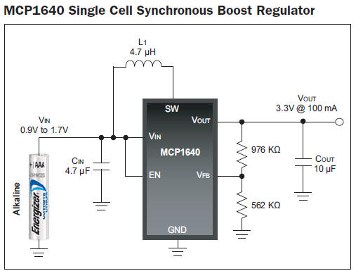
LED Lighting Design
GuideDriving LEDs with a Boost Regulator A boost
regulator topology is used when the output voltage of the converter
must be equal to or greater than the input voltage. A boost
regulator is useful for driving a chain of LEDs connected in series.
It is beneficial to drive multiple LEDs in series. This ensures that
all LEDs receive the same amount of current and will have the same
brightness level. Using a coupled inductor in the boost circuit
reducing the switching voltage requirements of the MOSFET switch.
The MCP1640 synchronous boost regulator can provide a stable
operating voltage for an LED from a single cell alkaline battery.
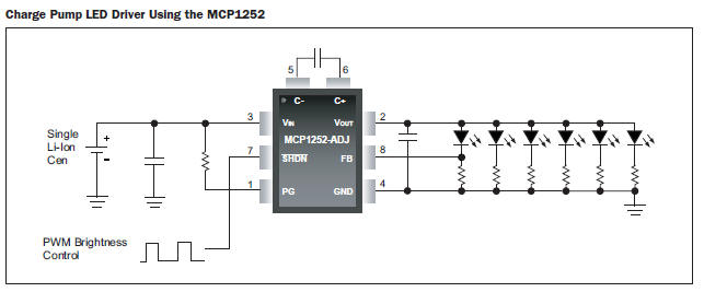
MCP1252 Charge Pump Backlight Demonstration Board (MCP1252DM-BKLT)
Demonstrates the use of a charge pump device in an LED application
and acts as a platform to evaluate the MCP1252 device in general.
Light intensity is controlled uniformly through the use of ballast
resistors. A PIC10F206 MCU provides an enable signal to the MCP1252
and accepts a push-button input that allows the white LEDs to be
adjusted to five different light intensities.
|
