Ringer circuit diagram
Download pdf:
TELEPHONE TONE RINGER circuit diagram UTC 31002A is a
bipolar integrated circuit designed for telephone bell replacement.
It can also be used as alarms or other alerting devices. Designed
for telephone bell replacement. The application circuit
illustrates the use of the UTC 31002A device in typical telephone
tone ringer application. The AC ringer signal voltage appears across
the TIP and RING inputs of the circuit and is attenua-ted by
capacitor C1 and resistor R1. C1 also provides isolation from DC
voltage (48V) on the exchanged line. After full wave rectification
by the bridge diode, the wave form is filtered by capacitor C4 to
provide a DC supply for the tone ringer chip. As this voltage
exceeds the initiation voltage (Vsi), oscillation starts. With the
components shown, the output frequency chops between 512Hz (FH1) and
640 Hz (FH2) at a 10 Hz (FL) rate. The loudspeaker load is coupled
through a 1300Ω
to 8Ω
transformer. The output coupling capacitor C5 is required with
transformer coupled loads. When driving a pizeo-ceramic transducer
type load, the coupling C5 and transformer (1300Ω:8Ω)
are not required. However, a current limiting resistor is required.
TONE RINGER circuit diagram WITH BRIDGE DIODE
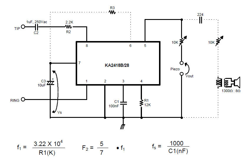
APPLICATIONS · Electronic telephone ringers · Extension ringers. The
KA2418B/28 is a monolithic integrated circuit telephone tone ringer
with bridge diode, when coupled with an appropriate transducer, it
replaces the electromechanical bell. This device is designed for use
with either a piezo transducer or an inexpensive transformer coupled
speaker to produce a pleasing tone composed of a high frequencys
(fH1, fH2) alternating with a low frequency (fS) resulting in a
warble frequency. The supply voltage is obtained from the AC ring
signal and the circuit is designed so that noise on the line or
variation of the ringing signal can not affect correct operation of
the device.
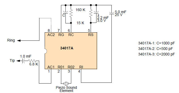
Telephone Tone Ringer
Complete Telephone Bell Replacement Circuit diagram with Minimum
External Components On-Chip Diode Bridge and Transient
Protection Direct Drive for Piezoelectric Transducers
Push Pull Output Stage for Greater Output Power Capability
Base Frequency Options 34017A-1: 1.0 kHz 34017A-2: 2.0
kHz 34017A-3: 500 Hz Input Impedance Signature Meets Bell and
EIA Standards Rejects Rotary Dial Transient
 |
